Custom Flight Controller Board for Rocketry
Introduciton
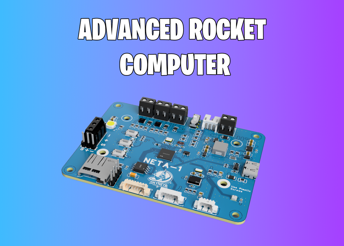
After weeks of design, simulation, and testing, I would like to share NETA-1, a 4-layer PCB built around the STM32F411CEU6 ARM Cortex-M4 microcontroller. It offers rich I/O capabilities and is optimized for reliable operation under high dynamic conditions. The board integrates sensor fusion, communication, storage, and actuation systems needed during a rocket’s full flight profile.
The PCB was fully designed in EasyEDA, taking into account signal integrity, power isolation, and high-current path management for mission-critical reliability.
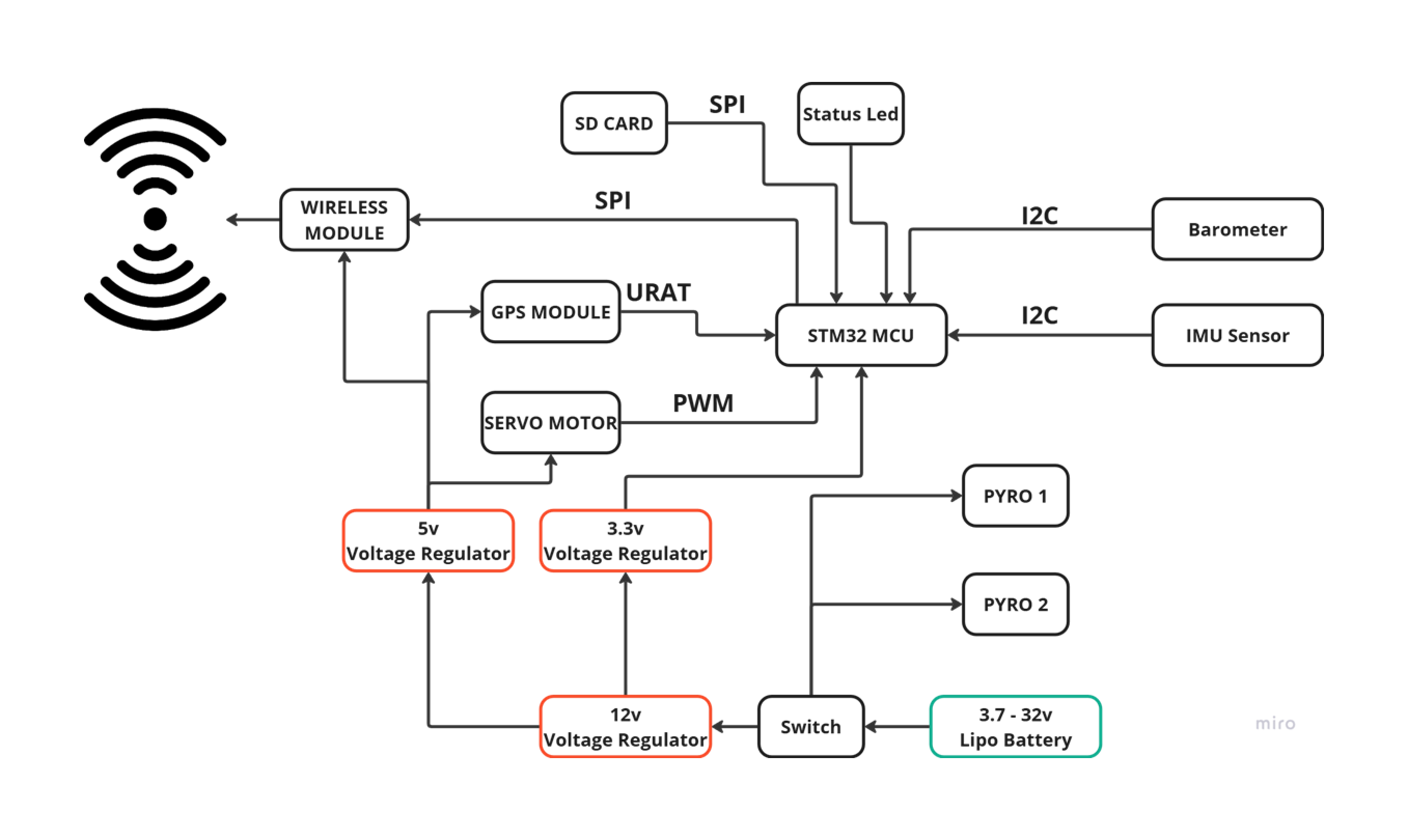
System Block Diagram
This is a basic diagram shows the flight borad system
Schematic Design
The first step is to connect all the components together with a schematic. I've included all the schematics down below in one image if you'd like to read them in full quality we all the pdf file in files section later.
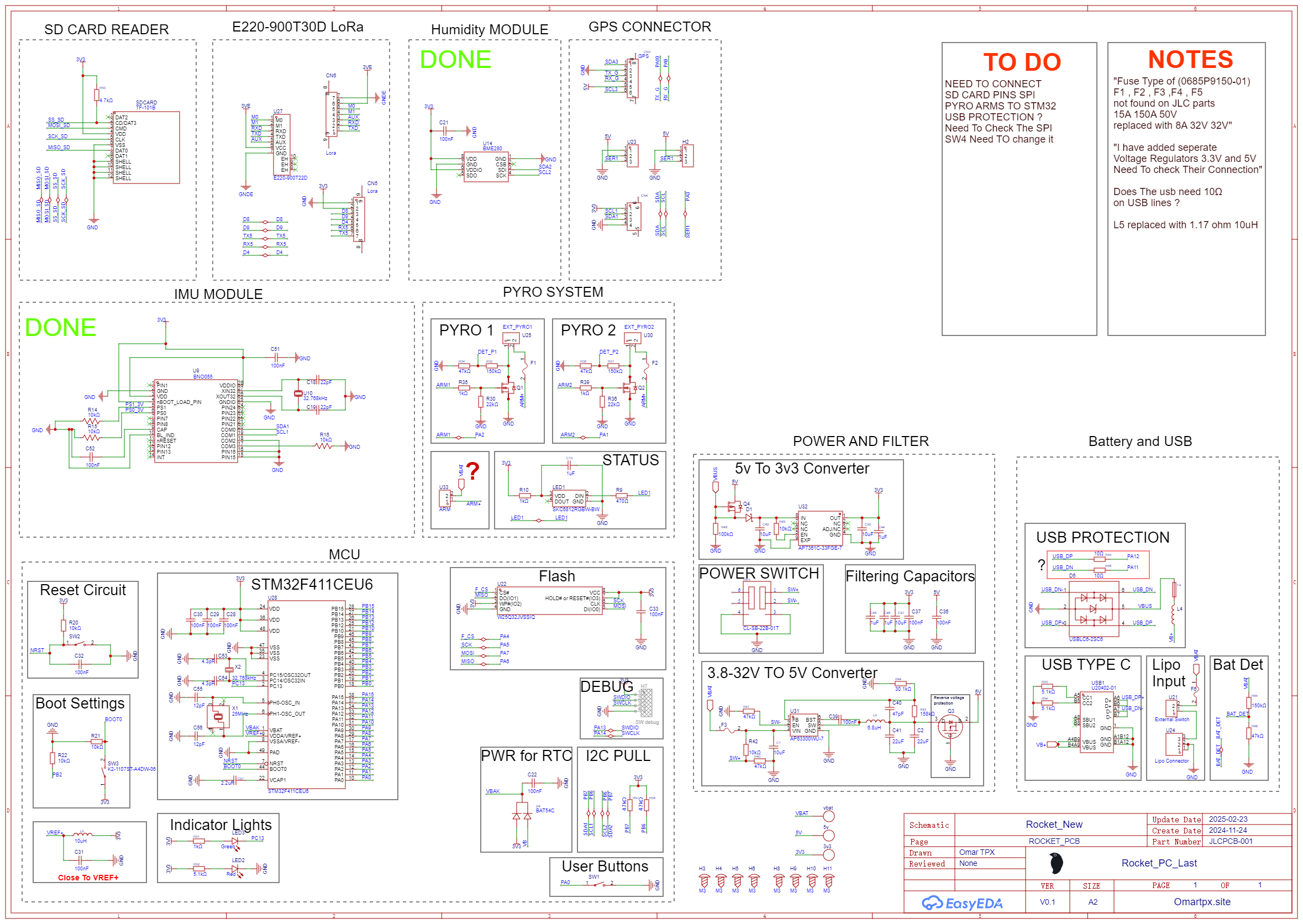
NOTE: The connection are not completely done. I will update the schematic soon so please check the TO DO and NOTES list on the right before use the board
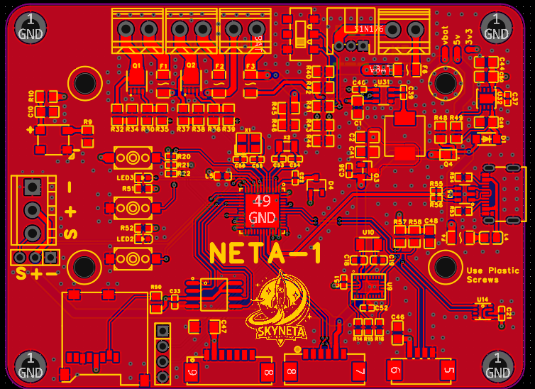
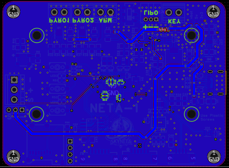
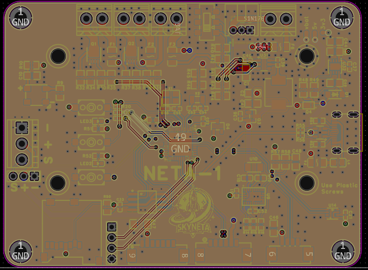
Layout
After finishing the schematic the next step is to begin routing the (PCB) where you take the electrically defined connections from the schematic and physically map them out. I'have tried to use only 2 layers but it didn't work since are the components are too many and the routes are many so i decided to make the board using 4 layers. The red side is the front copper layer for signal and ground routings, The grey side is second layer also used for signal routings filled with ground plane , The Green Layer is the 3d Layer contain 3.3V power plane and last the blue side is the back layer signal routings filled with ground plane.
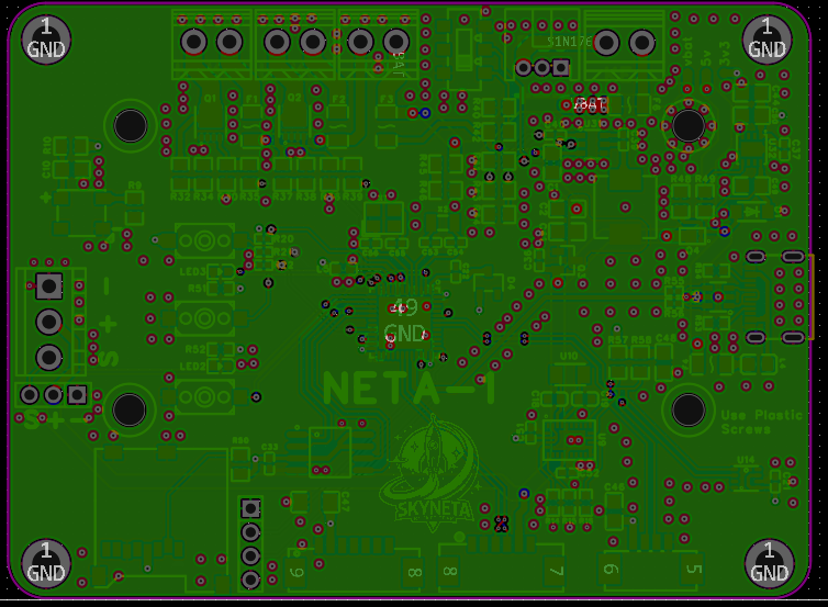
Everyone does it a bit differently but here's generally how we break down the process:
Define the board size. Place all your connectors (This usually defines how you interact with the board) Take special care to place and route your USB, RF, differential pairs, and high speed signals first When routing take note of pin assignments on chips that can be shifted to make routing easier
NETA-1 Design Specifics The layout for NETA-1 is a bit complicated because the design have very high current (Pyro 1 and Pyro 2 channels ) and sensetive signals (Sensors and other Interfaces) in the board and i have to find a way to manage them on a small sized board. Here's the general overview of what I did to prevent the noise :
I've increased the number of vias all around the high current components this will the minimize the noise around the components but this is still not enough to totally remove the noise so i have moved all the low signal components such as the sensors and the other interfaces away from the high current components. Finally and the most important way to prevent the noise is to split the grounds.
PCB Render
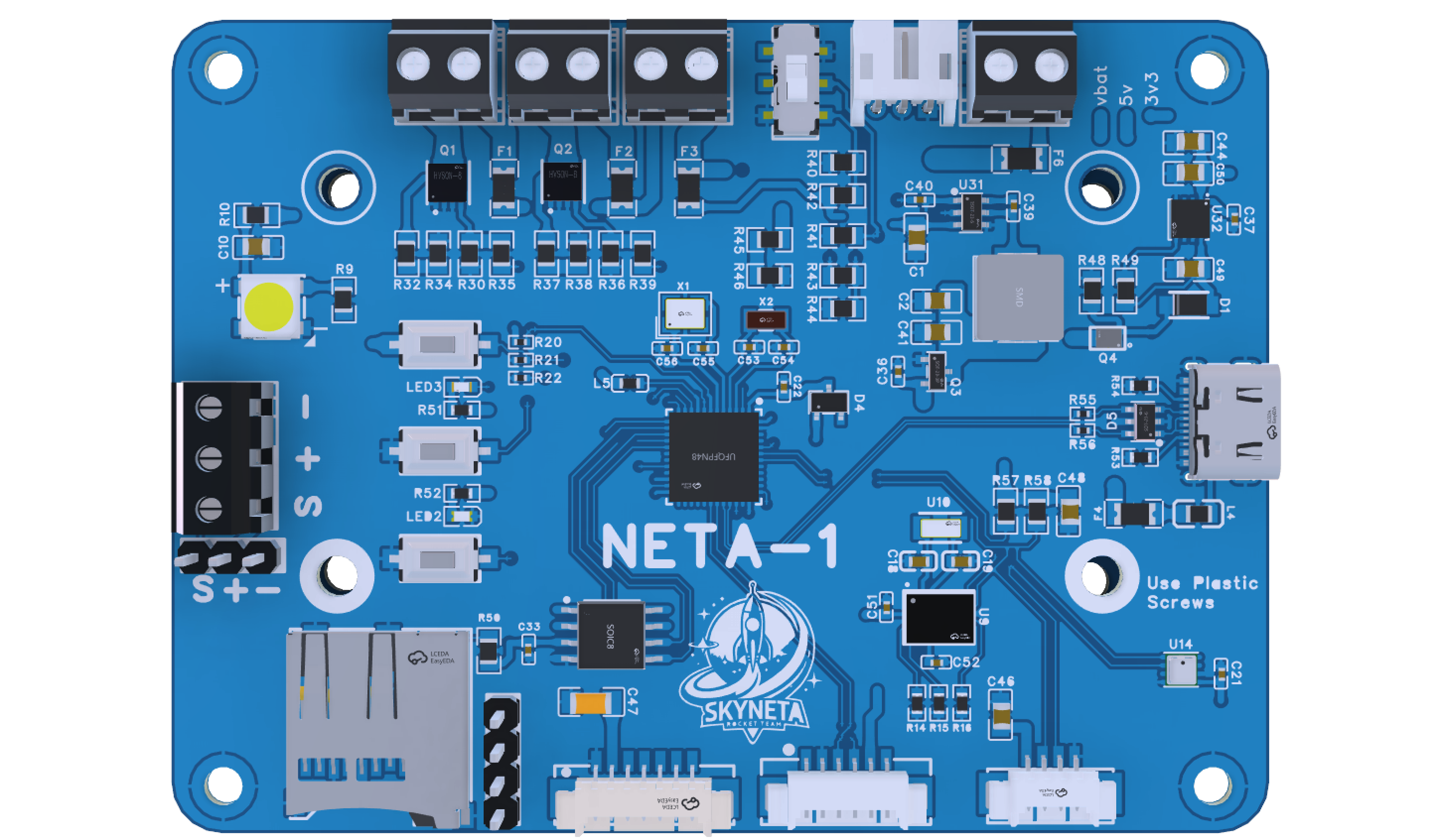
With the routing finished this is the final product ready for assembly. During the routing process it's often helpful to check the 3D model frequently to verify alignment between connectors and other components. These renders were made with fusion 360.
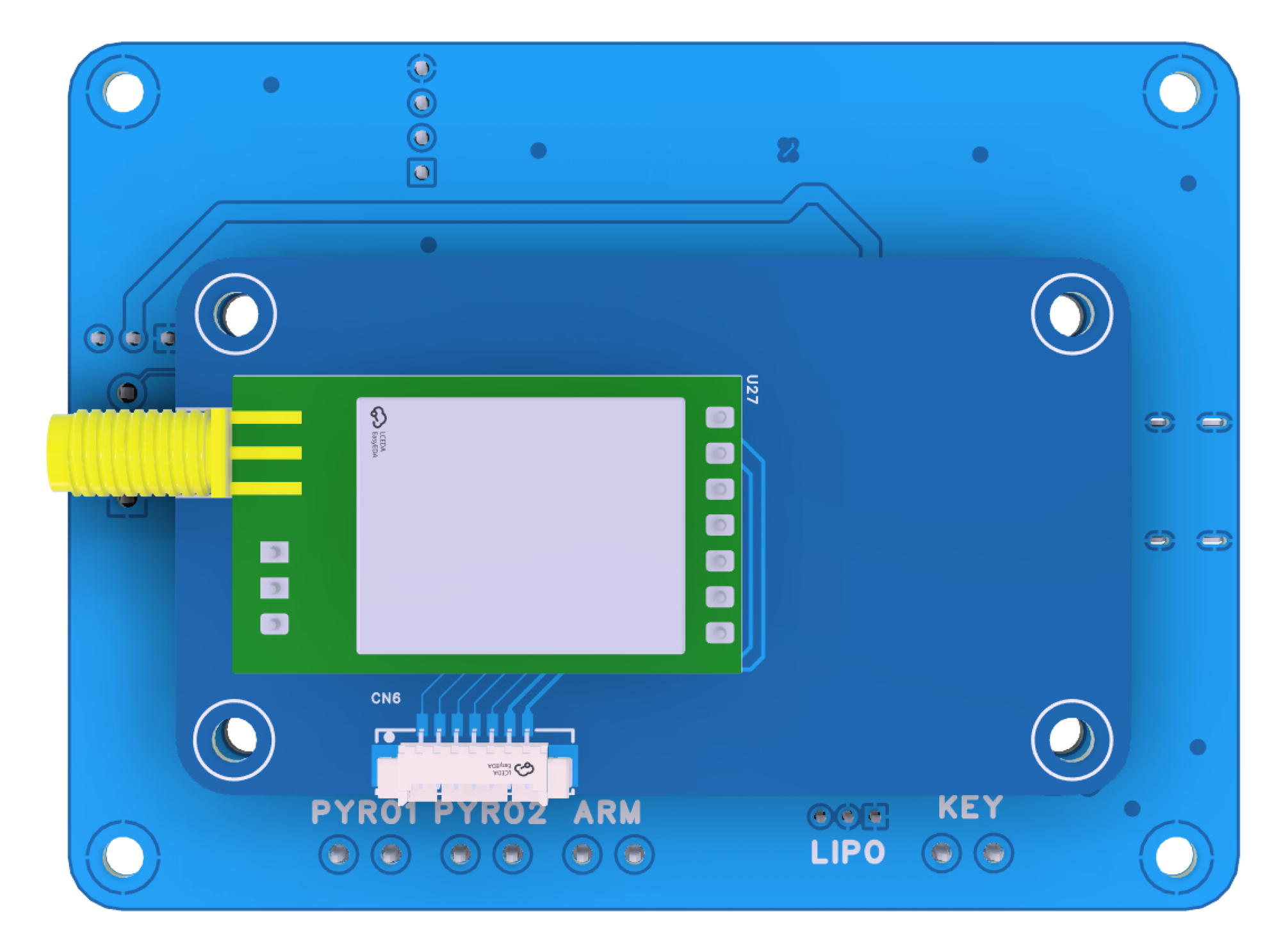
Back side of the board shows the mount place for the external wireless module
Used Components
1. Proccessor
STM32F411CEU6 MCU – 100 MHz, 512 KB Flash, 128 KB RAM, ARM Cortex-M4 core with FPU
2. Telemetry & Positioning
Wireless Module (External): EBYTE E220-900T22D (LoRa, UART-based, long-range support)
GPS Module (External): BN-880 with concurrent GNSS and magnetometer support
3. Sensors
BNO055 – IMU with onboard sensor fusion (accelerometer, gyroscope, magnetometer)
BME280 – Barometric pressure and temperature sensor
4. Pyrotechnic Channels
Dual pyro channels (PYRO1, PYRO2) with dedicated MOSFET switching and high-current traces
Designed for deployment control (parachute, separation events)
5. Storage & Interfaces
Micro SD Card – SPI-based logging for full mission telemetry
UART – GPS and LoRa data reception
I2C – IMU and barometer communication
SPI – SD card logging
PWM – Servo motor control (e.g., fin actuation)
6. Power & Protection
Input Voltage: 3.7V to 32V Li-Po (XT30/XT60 input ready)
7. Onboard Voltage Regulators
12V for high-power peripherals
5V for logic and sensors
3.3V for MCU and low-power sensors
Reverse polarity protection
Overcurrent protection fuses
Dedicated power rail filtering and decoupling
The External modules (LoRa + GPS) can be screwed onto the back of the PCB via standoff-compatible headers for rugged integration.
Ground Station
While the NETA-1 board handles all data acquisition and control onboard, I've also developed a dedicated Electron.js application for Real-time telemetry visualization, GPS tracking, Pyro status monitoring
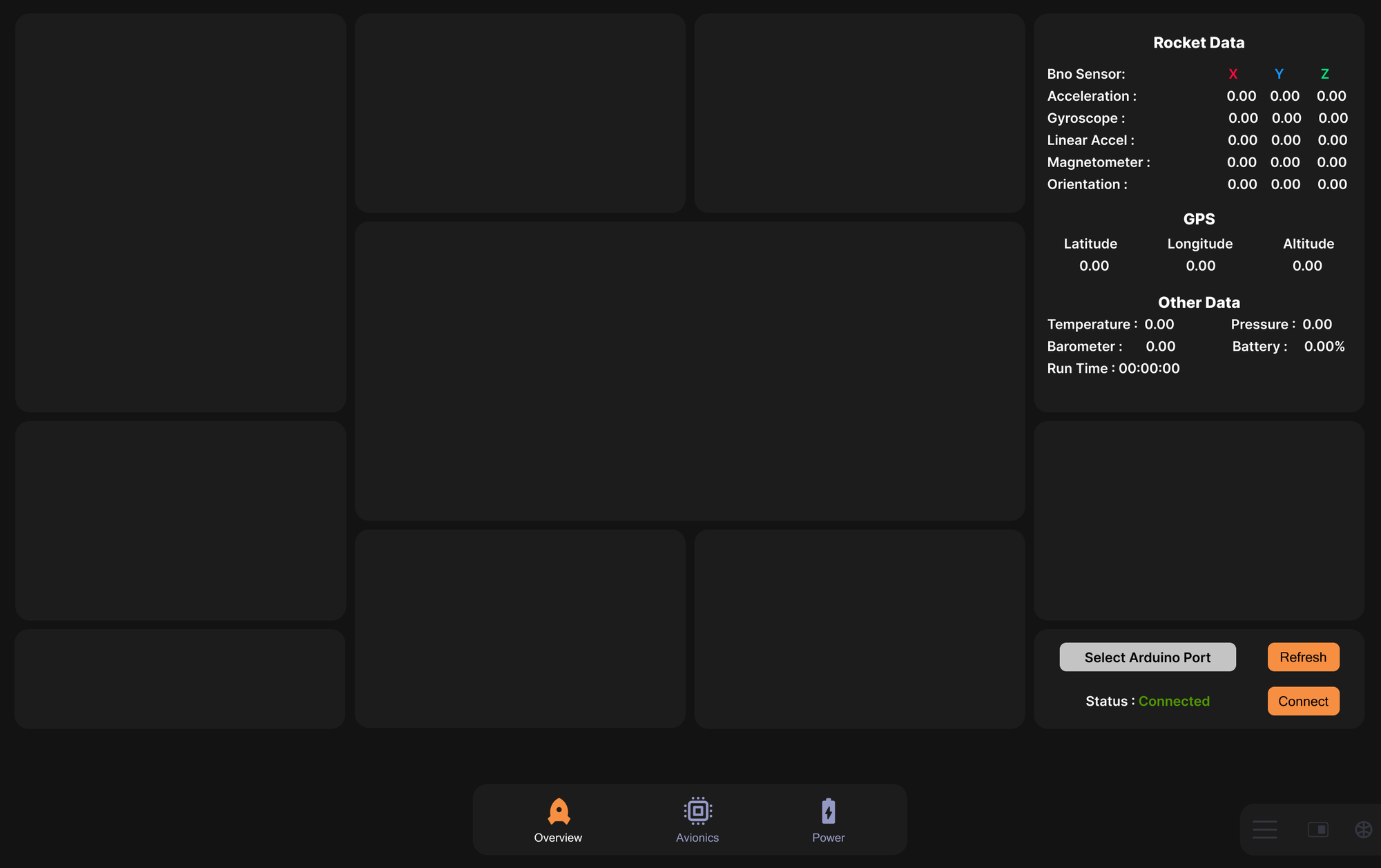
A full breakdown of the desktop application will be shared in a separate technical post.
Summary
| Feature | Specification |
|---|---|
| MCU | STM32F411CEU6 |
| IMU | BNO055 |
| Barometer | BME280 |
| Wireless Comm | E220-900T22D |
| GPS | BN-880 |
| Power Input | 3.7V – 32V Li-Po |
| Pyro Channels | 2 (High-current MOSFETs) |
| Data Logging | Micro SD (SPI) |
| Interfaces | UART, SPI, I2C, PWM |
| Software | Electron.js desktop app |
Feel free to reach out if you want to collaborate, or if you're building a similar board and want to exchange insights.